Well, it’s finally time to do another long over-due mod.
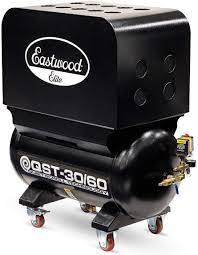
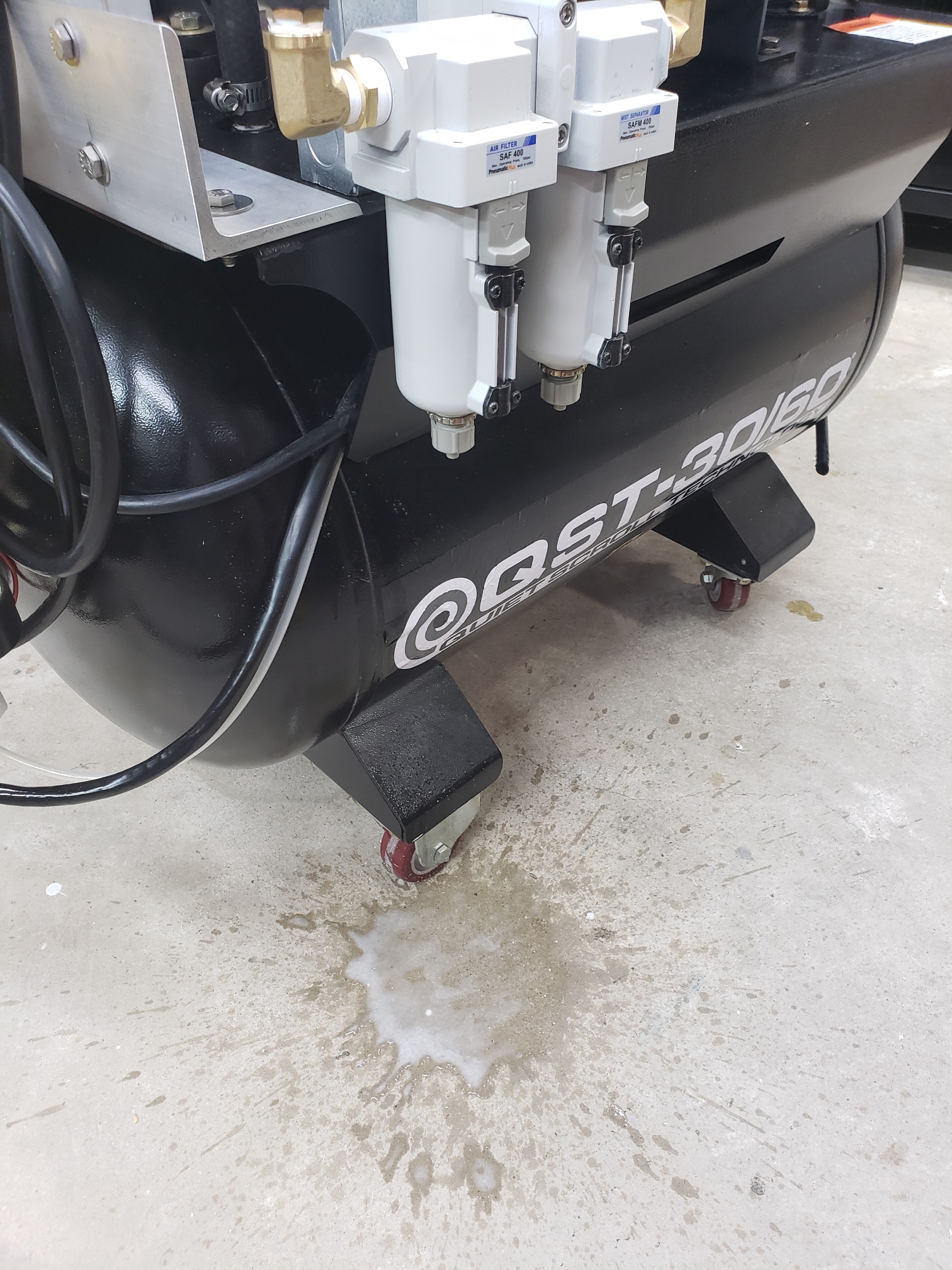
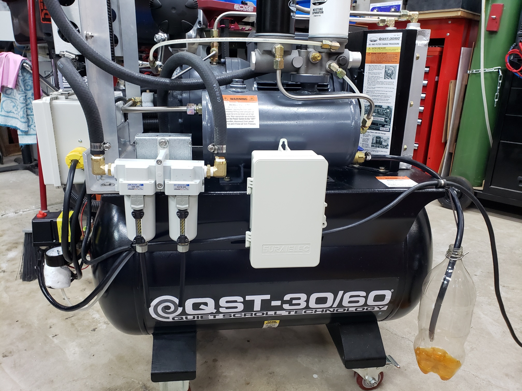
I recently forgot to turn off the air compressor (AC) one night and as you might guess Murphy got me. During the night one of the air hoses ruptured in the shop and caused the AC to run continuously until I found it the next morning. Needless to say this caused a mess filling the air lines with water. Luckily the AC (Eastwood QST 30/60) is rated for 100% duty cycle and it wasn’t hurt except that the oil and filters had to be changed.
Background
Air compressors create heat (>= 300 F) when compressing air to high pressure. Additionally, moisture from the ambient air being sucked in by the compressor is introduced into the air stream and will condense in the AC tank and lines, etc. if not dealt with. This is not usually a problem in daily shop work since I mainly only use blow guns and small air tools. But, in high duty-cycle applications like painting or media blasting this is a particular problem as the compressed air temperature can be very high causing the moisture to be moved from the tank into the lines where it will condense.
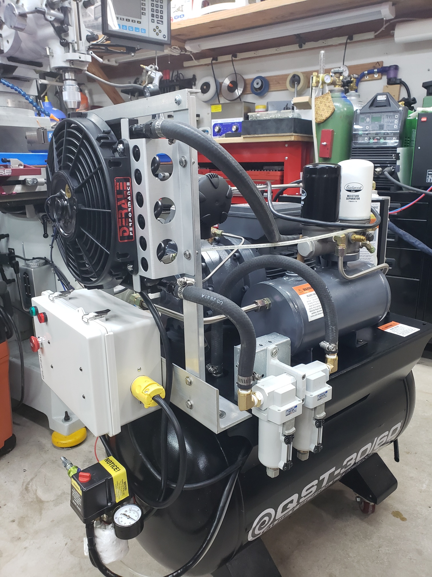
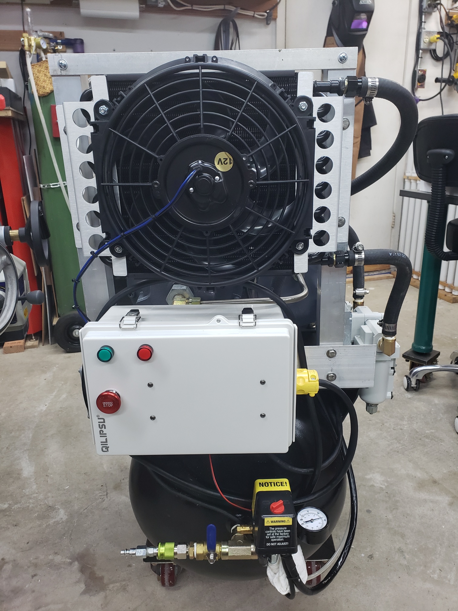
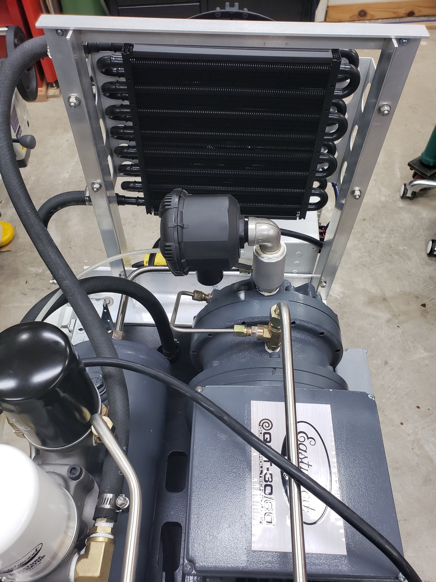
So, how to deal with this moisture in the air stream? There are many ways but, I choose to install an automotive oil/transmission remote cooler with a motorized fan (aka after-cooler). This unit is installed between the compressor outlet and the air tank. In addition I installed a water separator/oil filter unit on the cold end of the after-cooler. I also installed a desiccant air dryer in the main air line and a 24 hour On/Off timer.
Installation
Is straight-forward and not complicated. I used 1.5 x 1.5 inch and 3 x 3 inch aluminum angle to mount the cooler to the AC base plate using the original attach holes for the now unused AC top cover. New plumbing for the air is as follows:
– Remove air discharge line from the water/oil filter block and the tank (caution make sure the tank is depressurized before removing this line).
– Remove the fittings the line was attached to.
– Install new NPS/NPT fittings where the line was removed.
– Install new 1/2″ barb fittings and into the fittings installed above.
– Install high pressure line/hoses as shown in the images below.
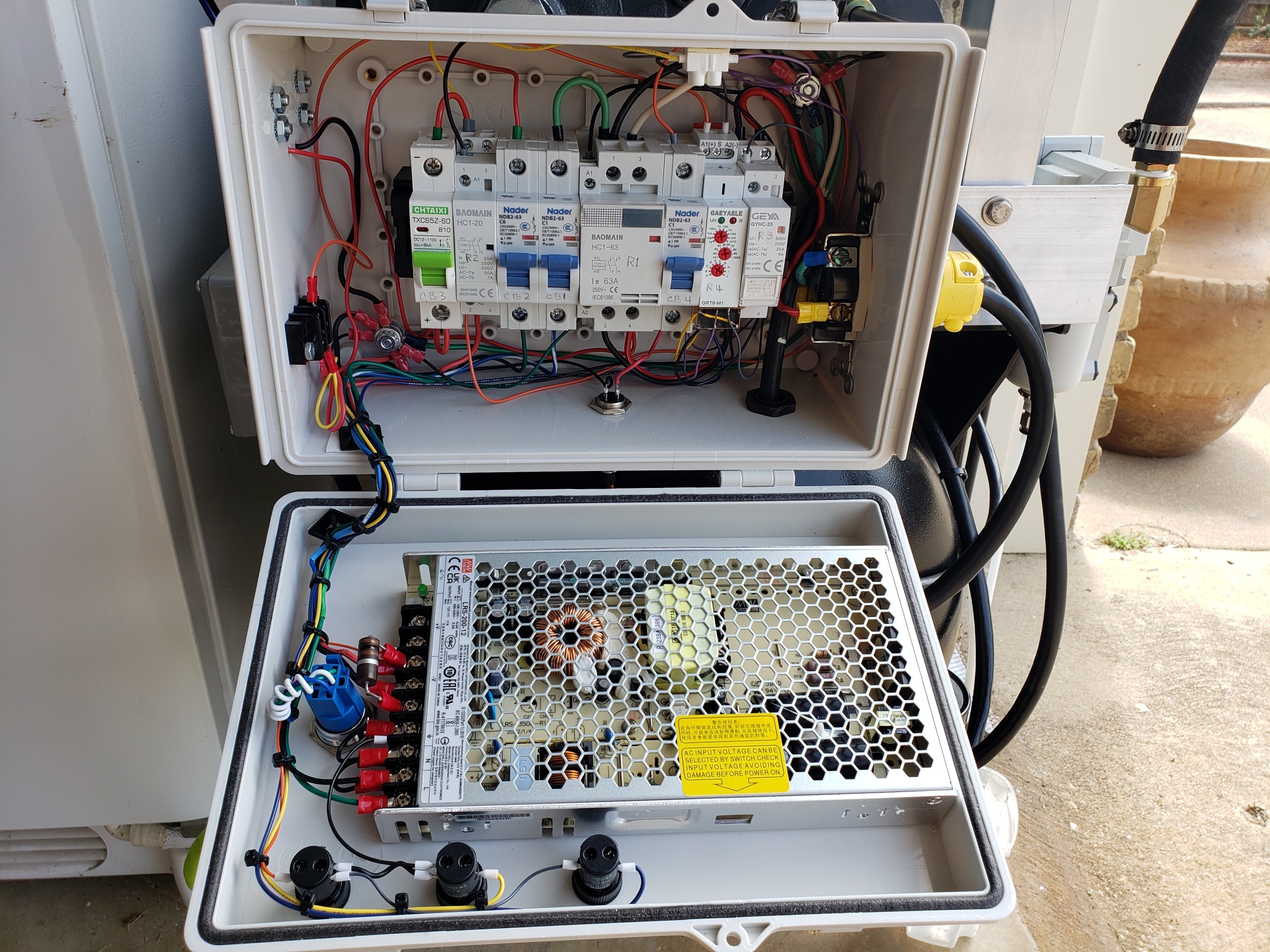
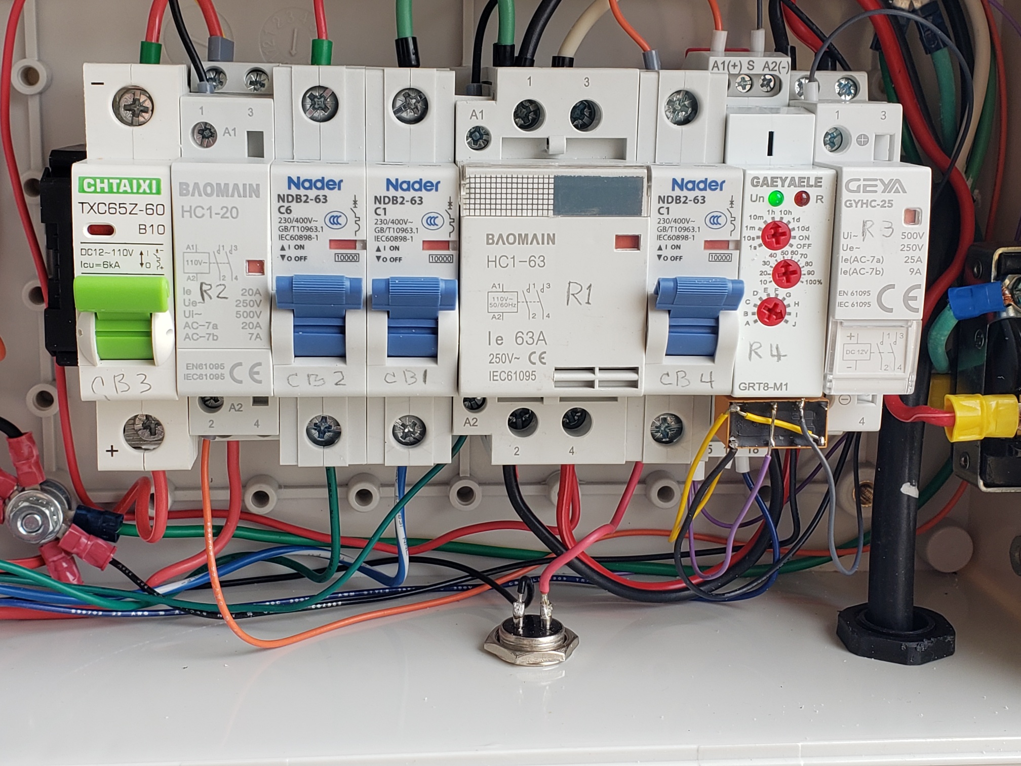
Control Box
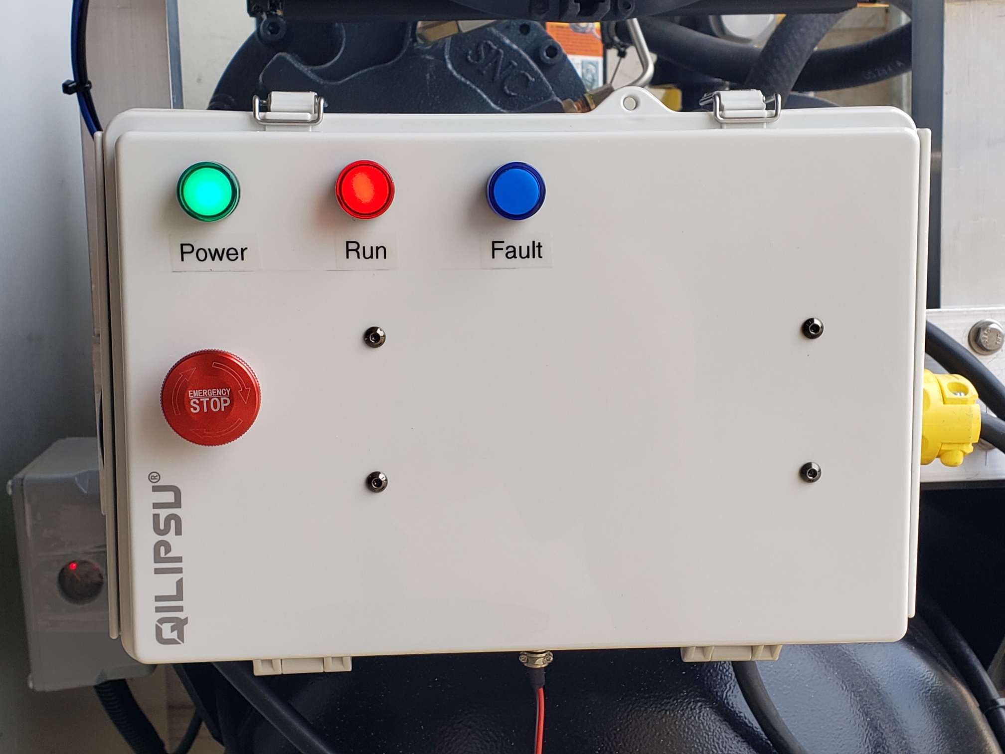
Since the after-cooler fan is 12 vdc a power source is necessary to power it and an enclosure to house it. I also elected to provide some power components for the compressor as I have never liked using the red switch on the AC control box to turn the AC on/off. So, I added some contactors, circuit breakers, a switch and a trio of LED indicator lights. See the schematic diagram for details of components and their function.
Note: If there should be a failure in the control box or after-cooler you can just plug the AC back into the mains power and use as originally configured.
Other Mods
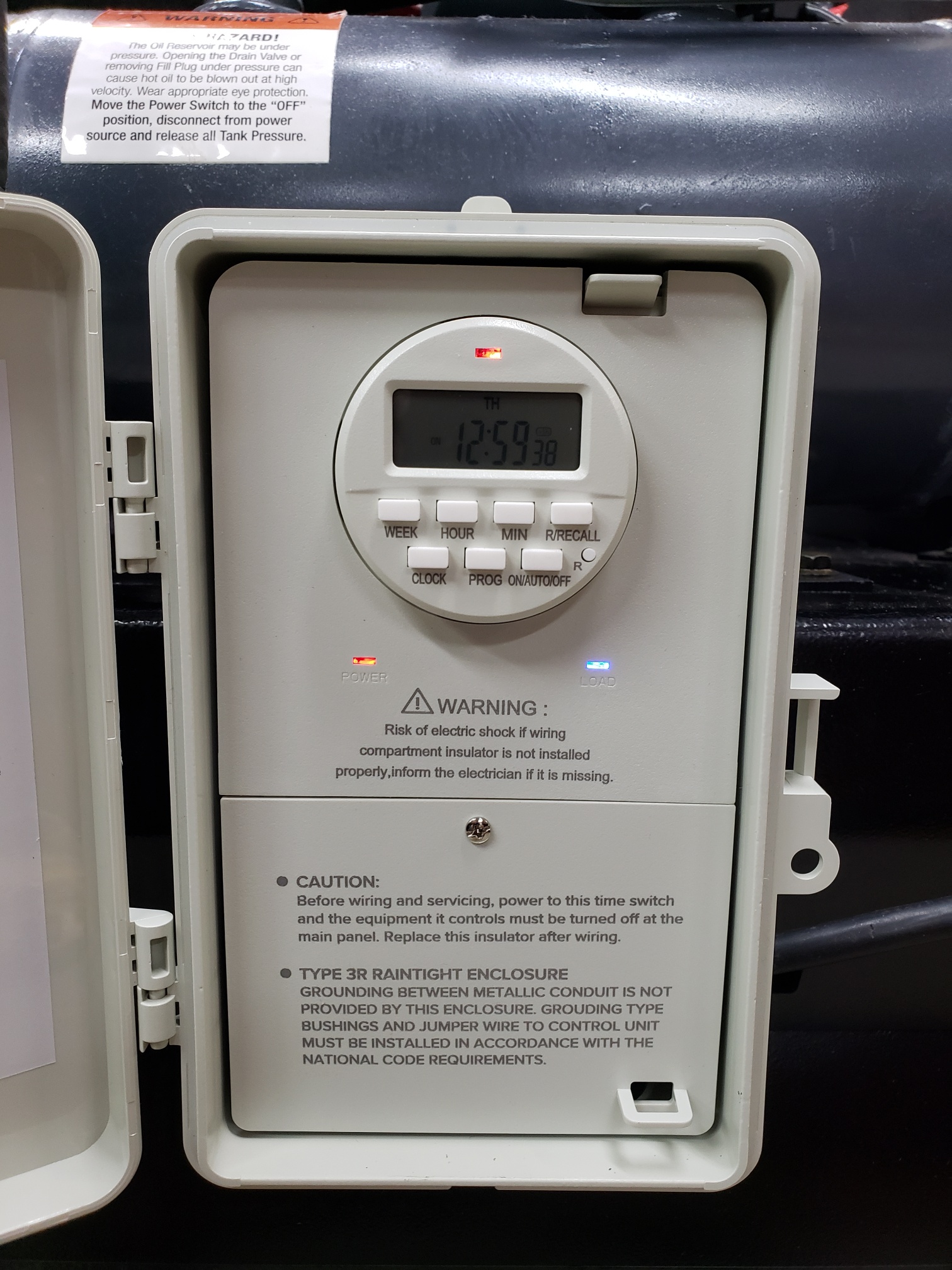
24 hour timer:
This timer is used to set the on/off hours the AC is powered up. This is purely a backup in case I forget to turn it off at night and it makes me feel better.
Compressor Run Timer:
In addition to the 24 hour timer this timer was added to shut the compressor off in case an air line ruptures during working hours. See the 2nd page (Theory Of Operation) of the schematic diagram for a detailed description of operation.
Automatic tank drain:
This drain will open for 2 seconds when the AC first starts to remove any water that is in the tank not caught by the water separator.
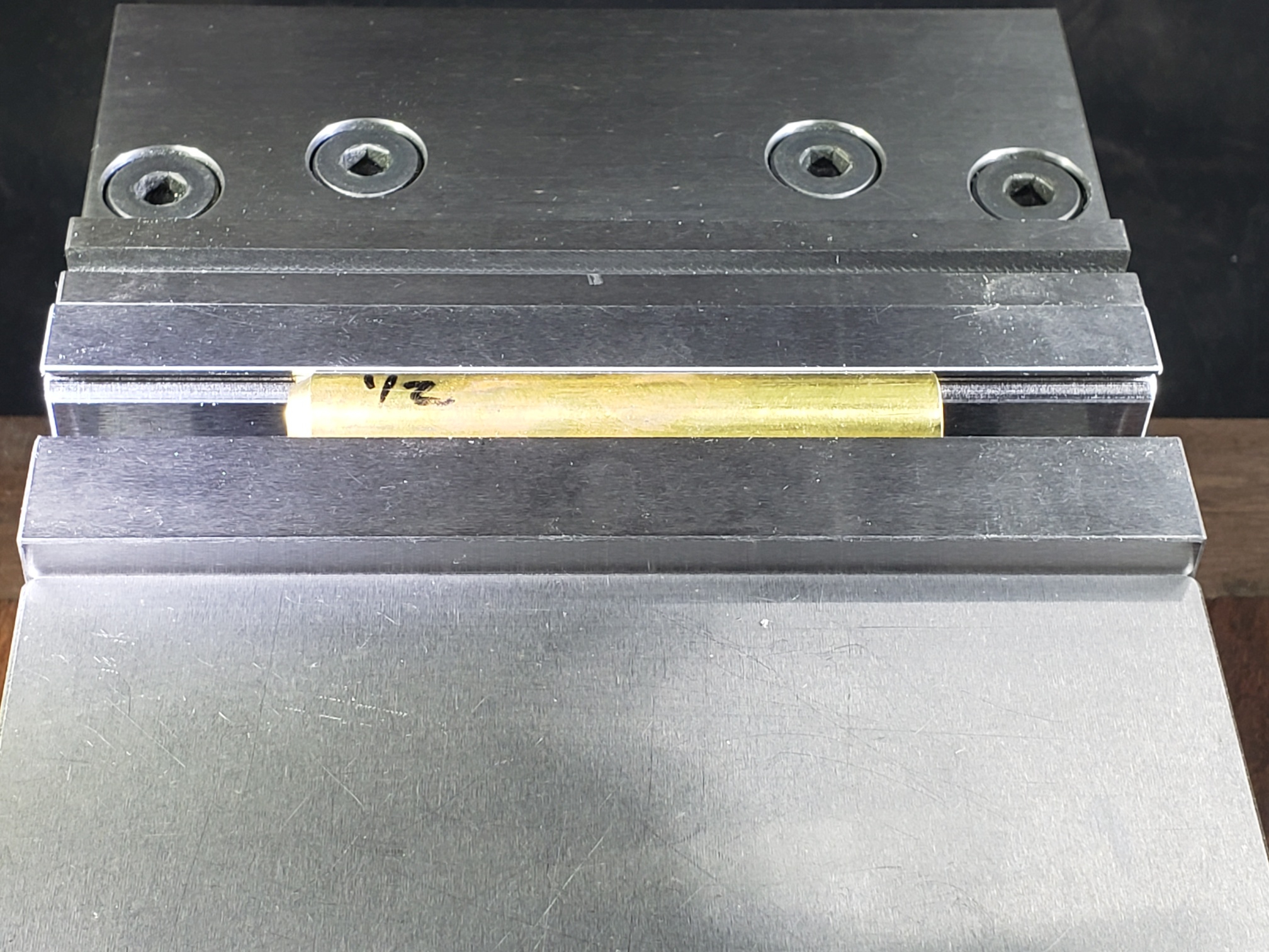
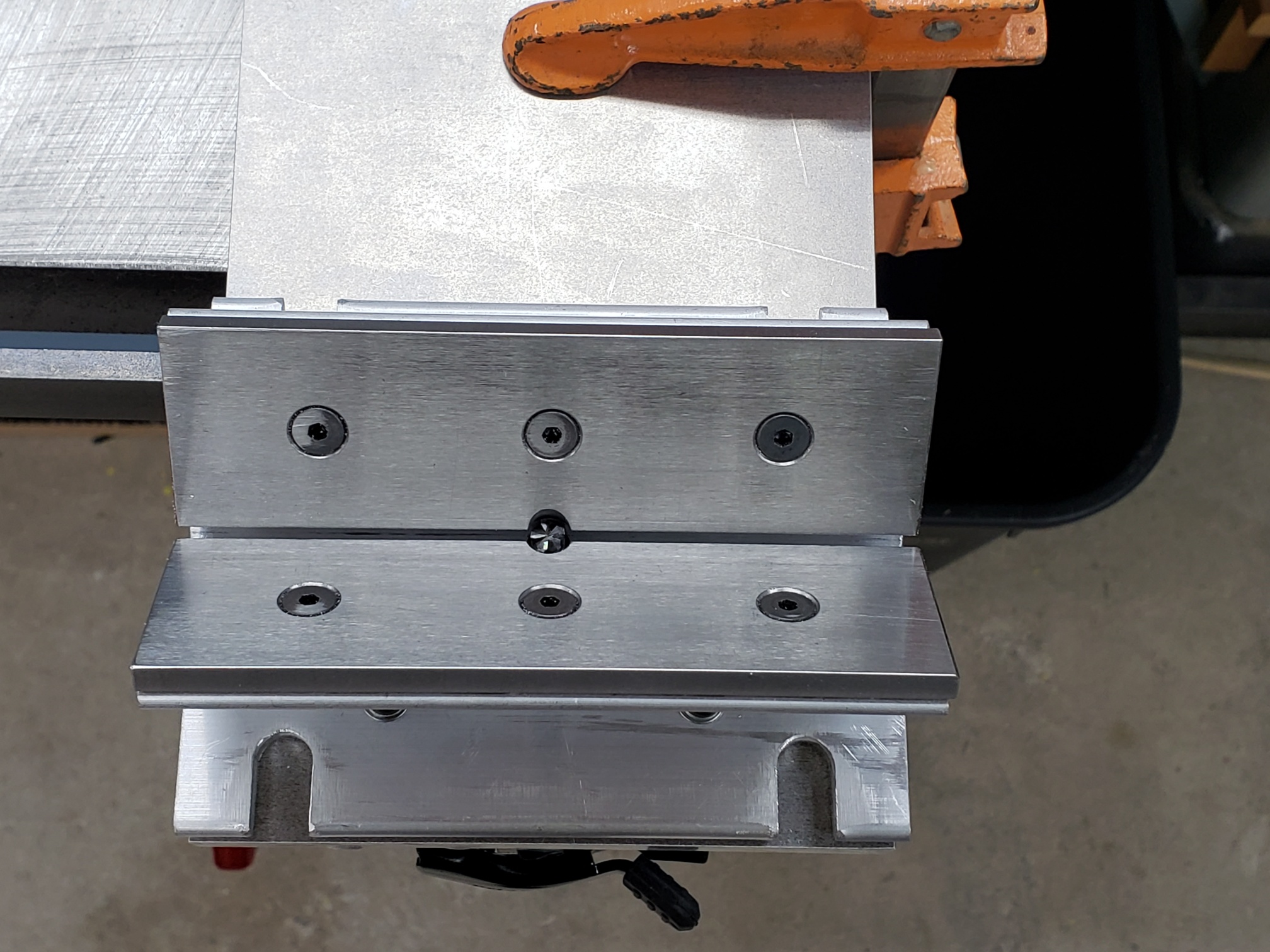
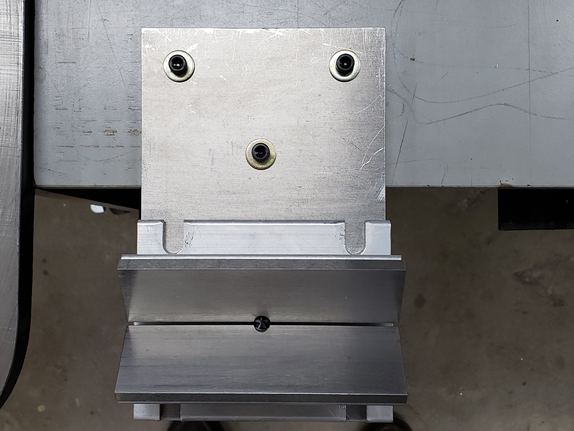
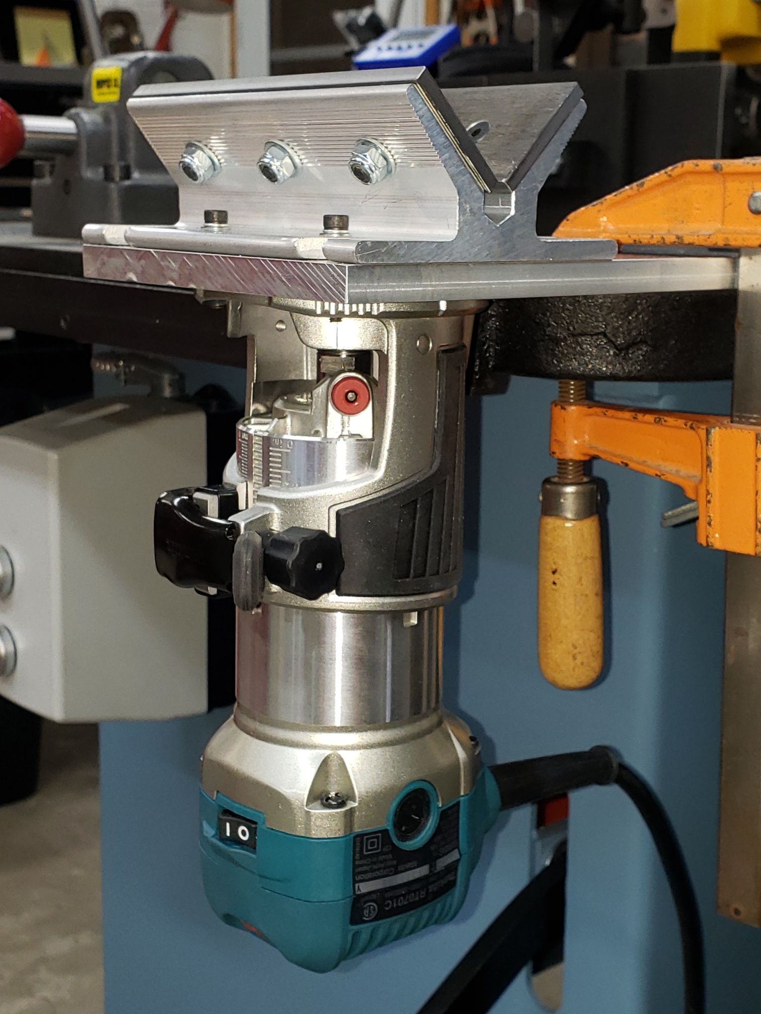
Picture Gallery
(click image to enlarge, hit back button to return)
Final Thoughts
I’m happy with the results of this mod and would do it again no question.
And, for those that are anal about leaving the cover off, Eastwood recommends once a month draining water from the oil tank. To do this requires removing the cover which is somewhat of a PIA. So, why not just leave it off as they mention in the video.
(Update 7/18/2023: Eastwood no longer sells the compressor with the cover. They didn’t say why, but I suspect it was due to cooling issues.)
If you own an air compressor be sure to at least drain the tank regularly to prevent rust and moisture in the system. If you need dry air other methods are needed and vary depending on the requirement.