Overview
This is a project I’ve been wanting to do for a long time. Effectively, the timing gears are replaced with electronics that read the RPM of the spindle and synchronizes it to a stepper motor or servo that drives the Leadscrew which drives the carriage where the work is done. On most hobby lathes there is a set of gears (see pix #1 in the gallery) that must be changed to a specific set of gears depending on what feed speed or threading TPI (turns per inch) that is required for the job. Needless to say this gets to be a MAJOR pain even if the lathe has a gearbox to help.
The Designer
Thanks to James Clough (Clough42.com) who spent the time necessary to develop the hardware and software to accomplish this task. This was no simple undertaking and my hat is off to him for his effort and the expense required to get this done. He realized that a number of people would want to replicate what he did, so he put together a kit consisting of a control panel and a daughter pc board, that mounts on on a Texas Instruments micro controller board. These items would have been a real problem for most users to get sourced and assembled. He also produced a very comprehensive series of videos detailing his design and implementation of this project which is immensely helpful. Many kudos James, you are the man.
Design Decisions
My implementation is slightly different than what James did as my lathe is a little bigger (2hp). In my mind this requires a bigger stepper/servo motor than he used. I found out early-on that trying to find out how much horse power was required to run the drive system on my lathe was not going to happen. I did a lot of reading and Googling to no avail. I even called Grizzly tech assistance and they didn’t have a clue. So, what to do. I decided to try using a motor with 1/4th the horse power rating of the main spindle motor and hope that would be enough. I settled on a Teknic ClearPath servo motor CPM-SDSK-3446P-RLN. This servo is rated at 1/2hp continuous and ~1hp intermittently. So far it has proven to be more than adequate for the job.
Installation
Encoder – The encoder installation was, for the most part, pretty straight-forward. One exception was the spindle gear. The spindle on this lathe is 52mm and finding a GT2 gear that would fit it wasn’t going to happen. So, I bought a pair of 100 tooth pulleys off eBay and machined out the center of one of them which wasn’t too bad after I found out these type pulleys are actually an assembly of a ring and a hub. Turns out the ring was almost the right diameter so not much machining was necessary.
Motor – Mounting the servo was easy as the old gear banjo fitting was ready made for the purpose. All you need is a couple of modified 1/2-13 5/8 t-nuts and a plate to mount the servo. I chose 5mm HTD pulleys/belt as I felt the 3mm hardware might be a little light.
Electronics – The micro controller is mounted in a die-cast aluminum box and is magnetically attached to the lathe’s electrical box. Quick-disconnect plugs were added for easy removal.
Control Panel – I used the same die-cast box recommended by James to contain the control panel. I made a small bracket that attached to the back of the box and added a magnet which is attached to the top of the spindle gearbox . The nice thing about the magnet is you can adjust it to obtaining the best viewing angle.
Stop Switch – The one addition I made to this project was to add a stop switch to the carriage. When turning to a shoulder this is a real benefit. All it requires is a micro switch (NO) that is movable in relation to the carriage and a small relay (NC) in the electronics box to interrupt the servo Ena- line. This switch works VERY well and will stop within a few thousandths every time. The stopping accuracy is somewhat governed by the leadscrew speed and depth of cut.
Warning! The stop switch CAN NOT be used for normal toward-the-chuck threading as the synchronization between the spindle and leadscrew will be lost when the motor stops. However, this is not a problem if you thread away-from-the-chuck as I do. Which, completely eliminates the pucker factor.
Settings
Program Code Settings
These are the settings I used in the configuration.h file
// Steps and microsteps
#define STEPPER_MICROSTEPS 3
#define STEPPER_RESOLUTION 800
// Step, direction and enable pins are normally active-high
#define INVERT_STEP_PIN true
//#define INVERT_DIRECTION_PIN true
//#define INVERT_ENABLE_PIN true
#define INVERT_ALARM_PIN true
// Enable servo alarm feedback
#define USE_ALARM_PIN
Gearbox Settings – I have to admit this took a while to figure out because of the multitude of setting possibilities that exist, but perseverance paid off. The following settings work out perfectly without having to use the STEPPER_MICROSTEPS_FEED and STEPPER_RESOLUTION_FEED variables in the program.
Turning: A D N T
Threading: B D 4 V
Conclusions
I’m more than pleased with the way this project turned out. Listed below are some of the high spots I found:
– No gear changing required.
– Able to change the carriage feed rate without stopping the lathe.
– Both SAE and Metric threading instantly available.
– Extra spindle power realized from not having to drive the leadscrew from the main motor.
Picture Gallery
(click image to enlarge, hit browser back button to return )
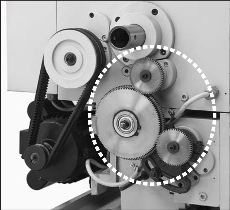
Before Modification 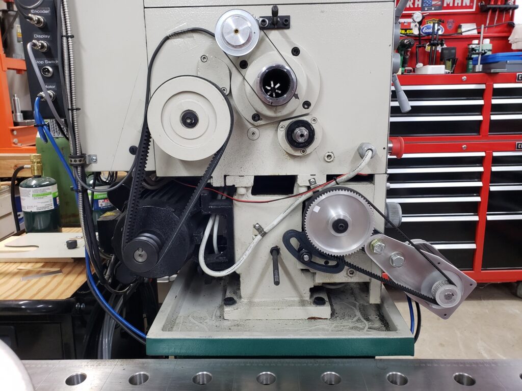
“Look Ma, No Gears!” 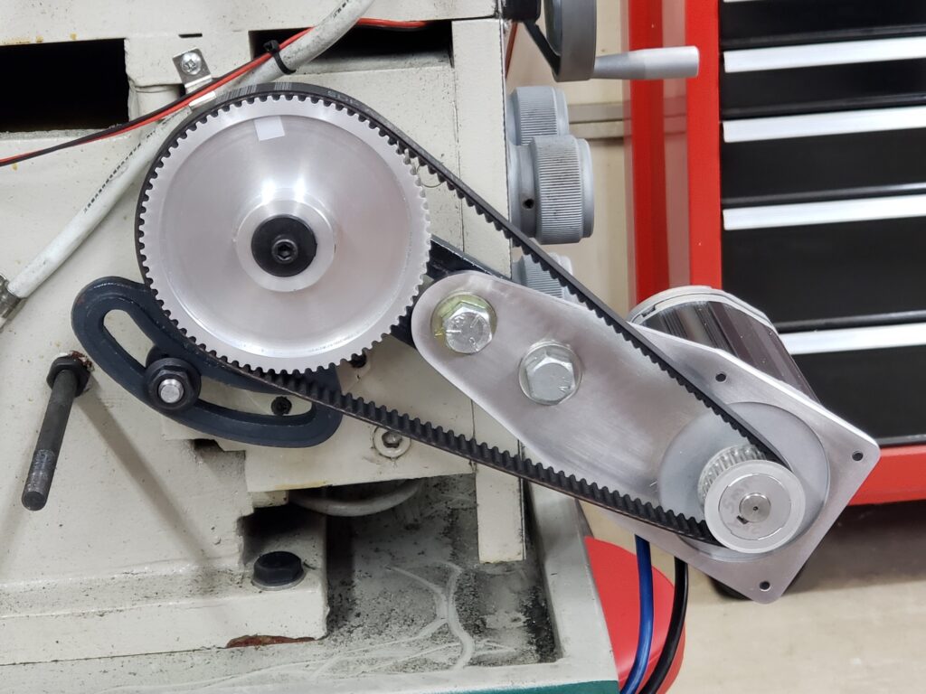
Motor, Pulleys & Belt 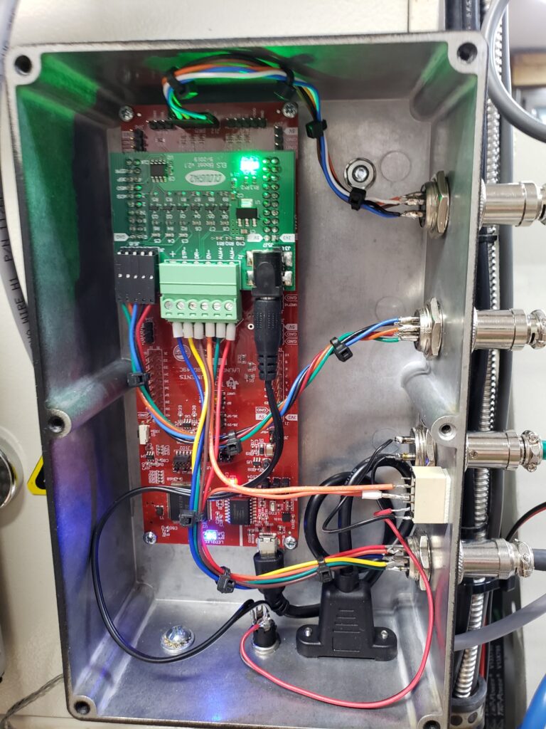
Electronics Box 
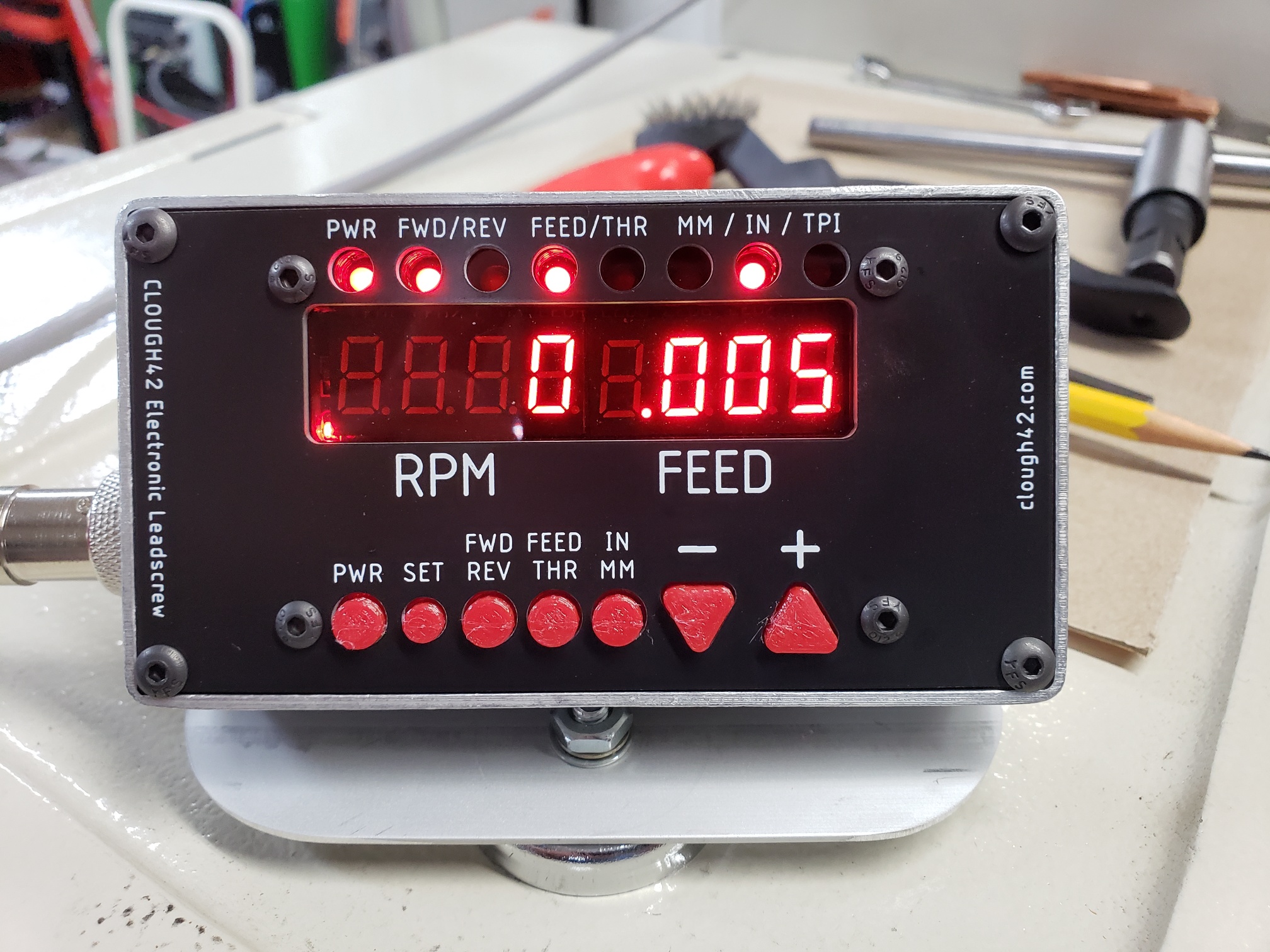
Control Panel/Display 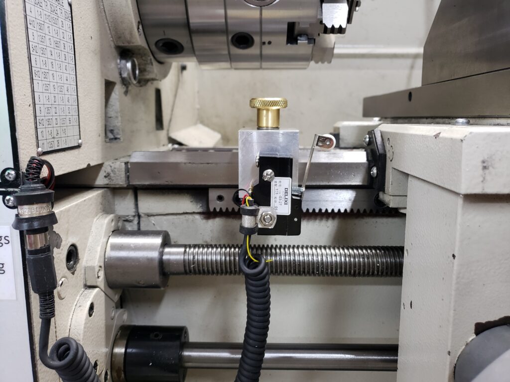
Stop Switch 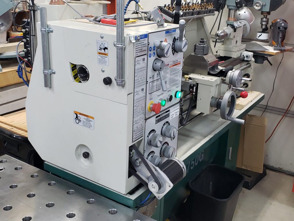
Modified Cover Installed 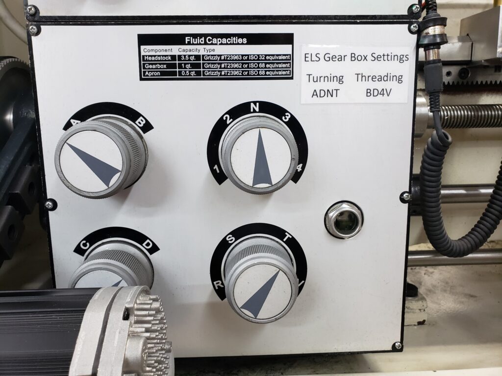
Gearbox Settings