Overview
While I was in the mood for modifying the lathe I added a Variable Frequency Drive (VFD) to it so I could vary the speed of the spindle without having to stop the lathe to change speeds.
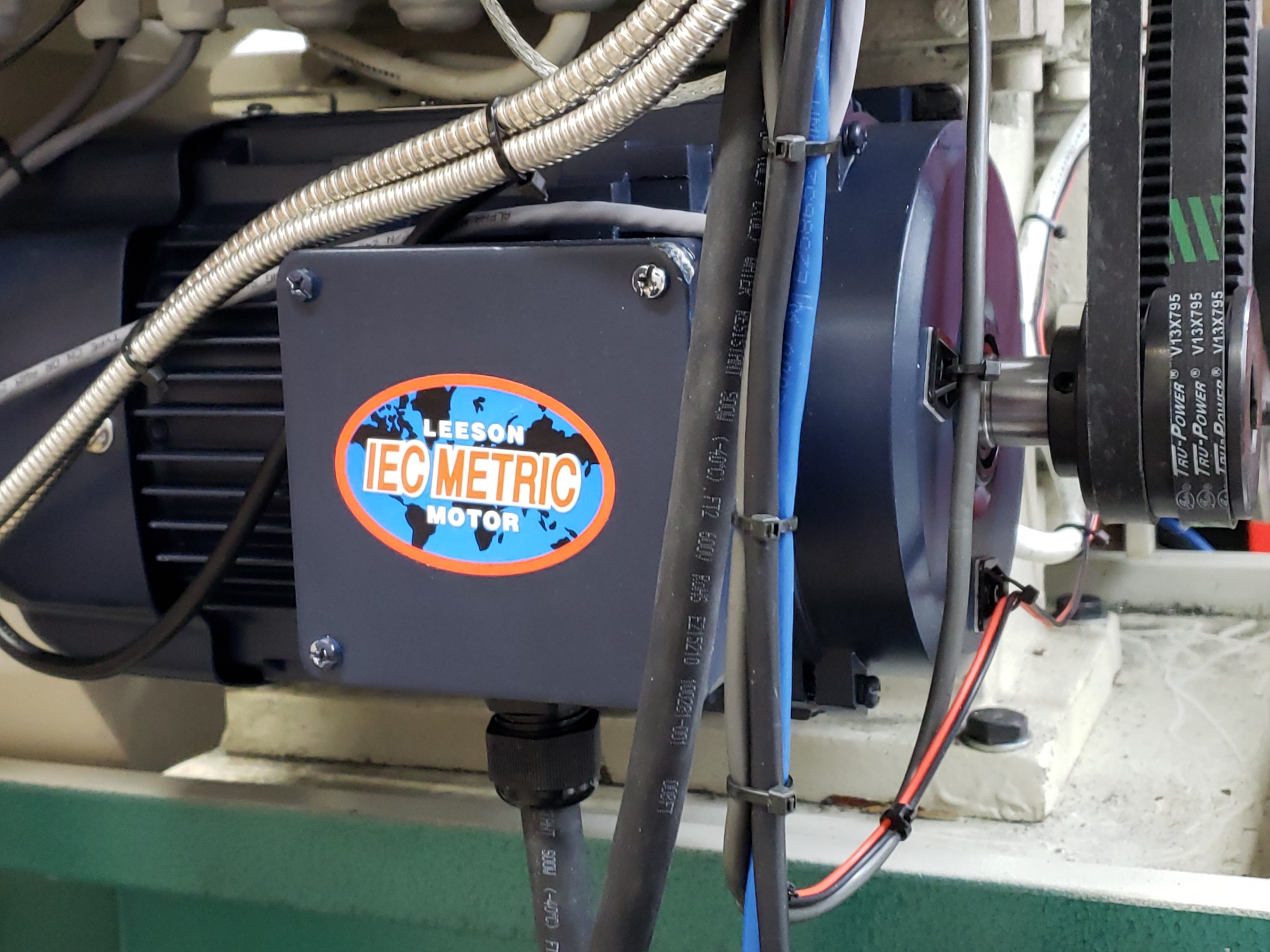
This mod was essentially straight forward since a direct replacement motor was available from Leeson that would just bolt up in place of the old one. A word of advice, this motor varies GREATLY in price ($300 – $2,000) so it pays to shop around.
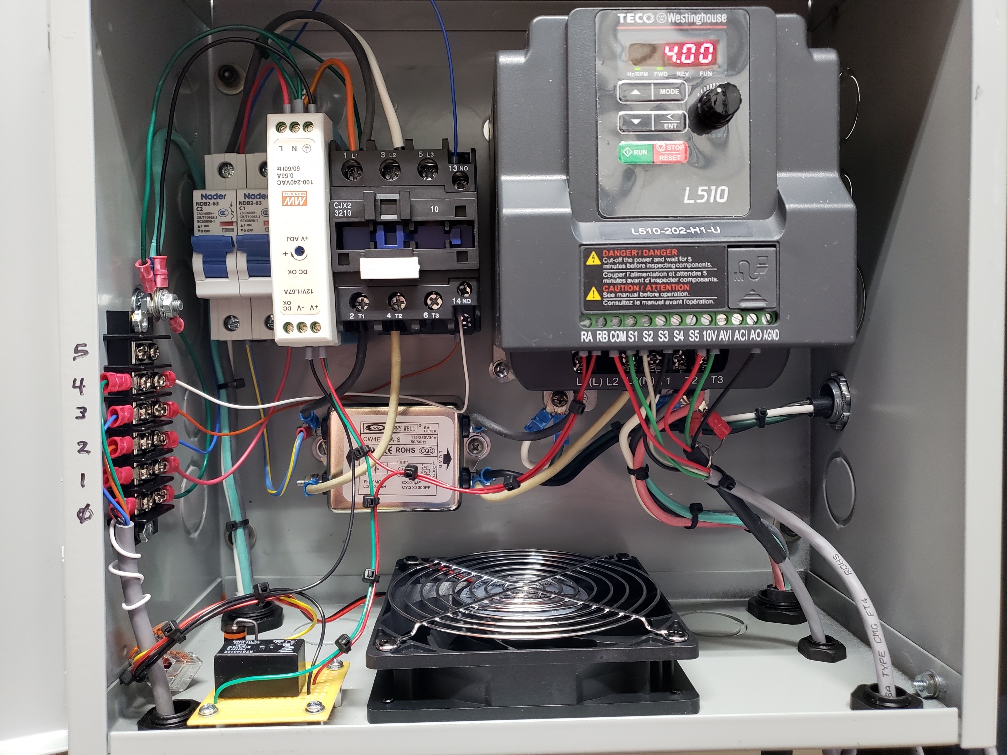
The other required major component was an inverter to provide the 3-phase variable speed drive for the motor. I chose the TECO-Westinghouse L510 . This inverter has dozens of parameters that can be programmed to control how the motor performance can be customized to your specific setup condition(s). Which is a really nice feature.
Installation
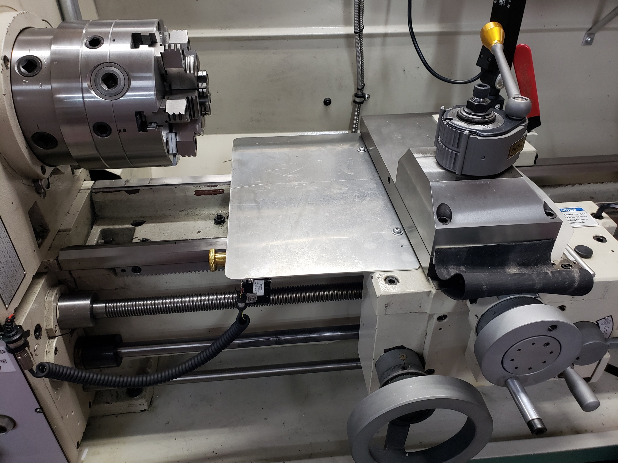
Changing the Motor – requires removing the chip guard in order to gain access to the motor mounting bolts. Also, a suitable 3-jaw puller (3″) is required to remove the motor pulley which is pressed on. When putting the motor pulley on the new motor use a series of 8mm bolts/washer to pull the pulley back on the shaft.
Caution: Don’t beat the pulley on with a hammer as it’s possible to damage the motor.
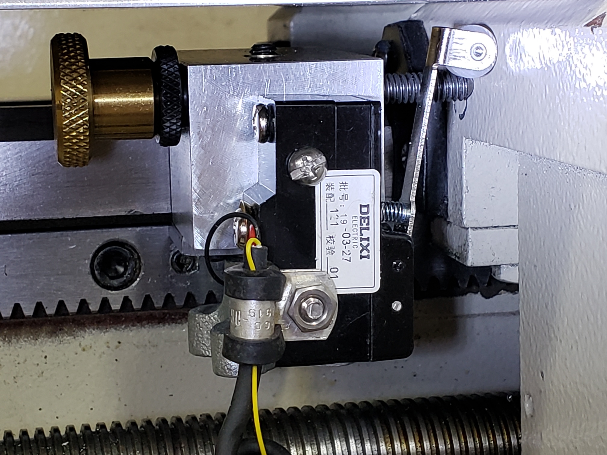
Control Wiring – I elected not to try and use the existing electrical controls in the electrical box on the back of the lathe as the method of control is quite different using a VFD. The way I did this was to only use the wiring for the push-button controls on the front of the lathe which terminate at a terminal board in the electrical box. After wringing out the controls wiring with an ohm meter I found I could use the existing wiring and lathe operating controls without any modifications at all. See the wiring diagram for details.
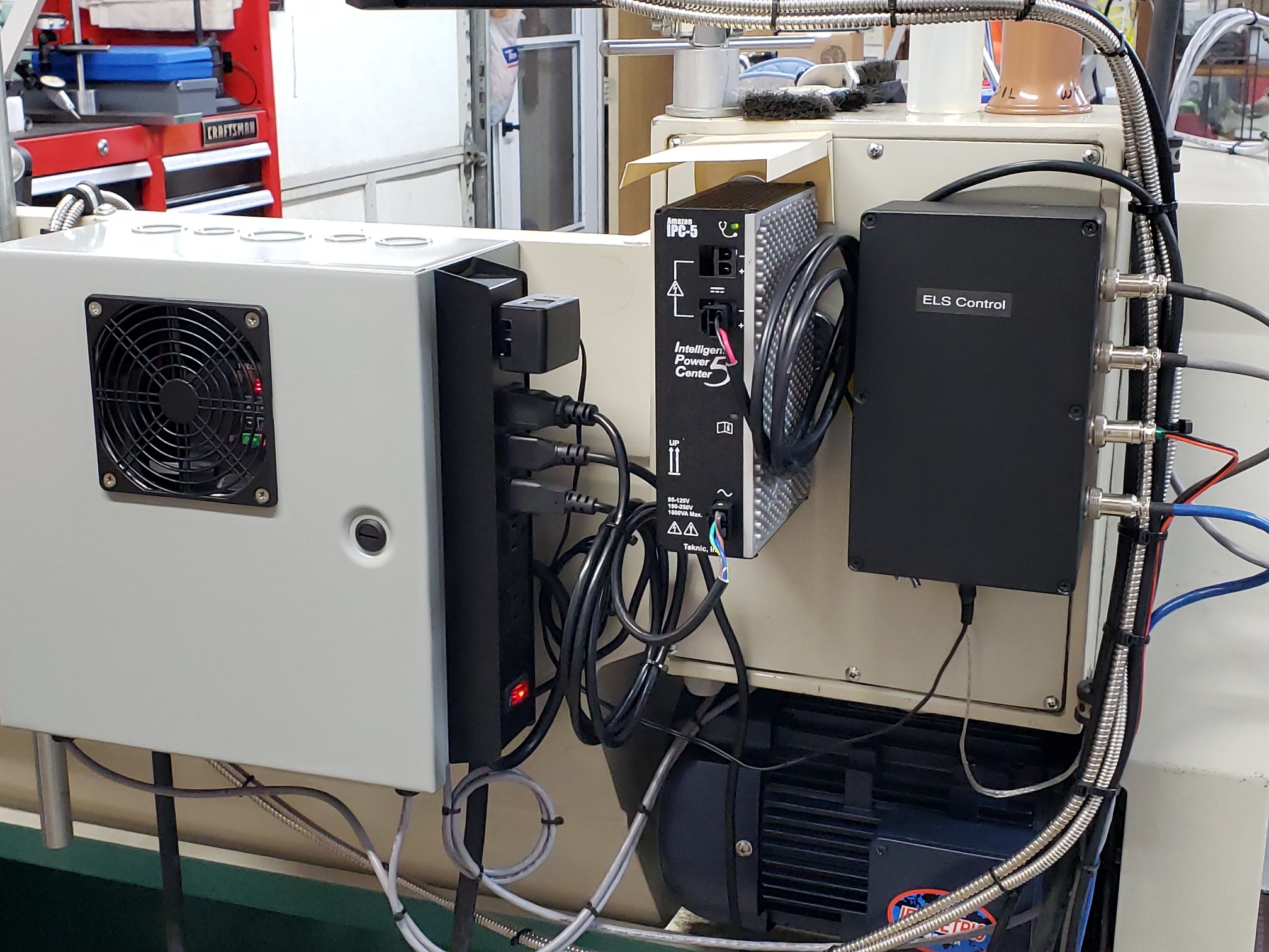
VFD Control Box – A suitable enclosure was needed to house the inverter and associated electrical controls. I chose a Hammond steel electrical enclosure based primarily on the inverter dimensions and the size of the other electrical components. The main components beside the inverter include DIN Rail mounted heavy duty (30 amp) AC contactor circuit breakers and a 12vdc transformer. A 30 amp EMI filter is bolted directly to the enclosure. The whole installation is pretty straight-forward. I also added a 5″ muffin fan to keep the inverter cool as it can generate some heat depending on how hard the motor is being used. This fan is setup to run at half speed when the lathe is not running and full speed (3500 rpm) when the lathe is running. Also, converting from single (1) phase to three (3) phase power is not 100% efficient. See the wiring diagram for details of how the whole system is wired.
Inverter Settings – These are the settings I used.
| Code | Para Name | Setting | Description |
|---|---|---|---|
| 00-00 | Control Method | 1 | SLV |
| 00-02 | Run Source | 1 | Ext Run/Stop |
| 00-04 | Ext Op Mode | 0 | Fwd Stop/Rev Stop |
| 00-05 | Freq Source | 2 | Ext AVI Analog Input |
| 00-12 | Freq Upr Limit | 60~ | Motor High Speed |
| 00-13 | Freq Lwr Limit | 4~ | Motor Low Speed |
| 00-18 | Jog Freq | 3.75~ | Jog Speed |
| 03-00 | Multi-Funct S1 | 0 | Fwd/Stop |
| 03-01 | Multi-Funct S2 | 1 | Rev/Stop |
| 03-03 | Multi-Funct S4 | 6 | Jog/Fwd |
| 03-11 | Output Relay | 0 | Run – (for Hi/Low Fan) |
Test Cuts
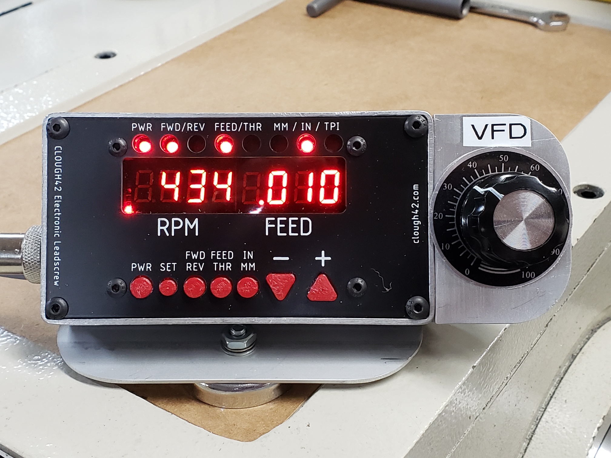
So far I’ve taken test cuts up to .250″ diameter with absolutely no pain or strain on the VFD or ELS. Here are the parameters I used for that cut:
2″ 12L14 steel bar, CNMG 432 insert, 700 RPM, .010 feed rate.
Note: My lathe uses a solid block in place of the compound slide which greatly stiffens the tool post. So this heavy a cut may or may not be possible using a compound.
Bottom line; the VFD and ELS are more than up to the job with room to spare. Very Cool!
Summary
This project was a fun and informative learning experience and I would do it again no question. Coupled with the Electronic Leadscrew (ELS) the Variable Frequency Drive (VFD) these two (2) mods have transformed the G0750G lathe into a very versatile and user friendly machine. I’m VERY pleased with the results.
Credits
Many thanks and appreciation go to James Clough for inspiring me to get off my butt and get started on this project that I’ve been putting off. His series of YouTube videos were very helpful and informative.
Picture Gallery
(click on an image to enlarge, hit the back button to return)