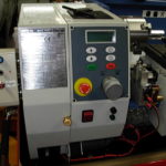
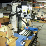
General
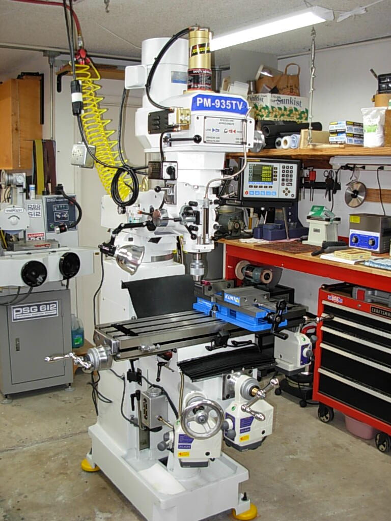
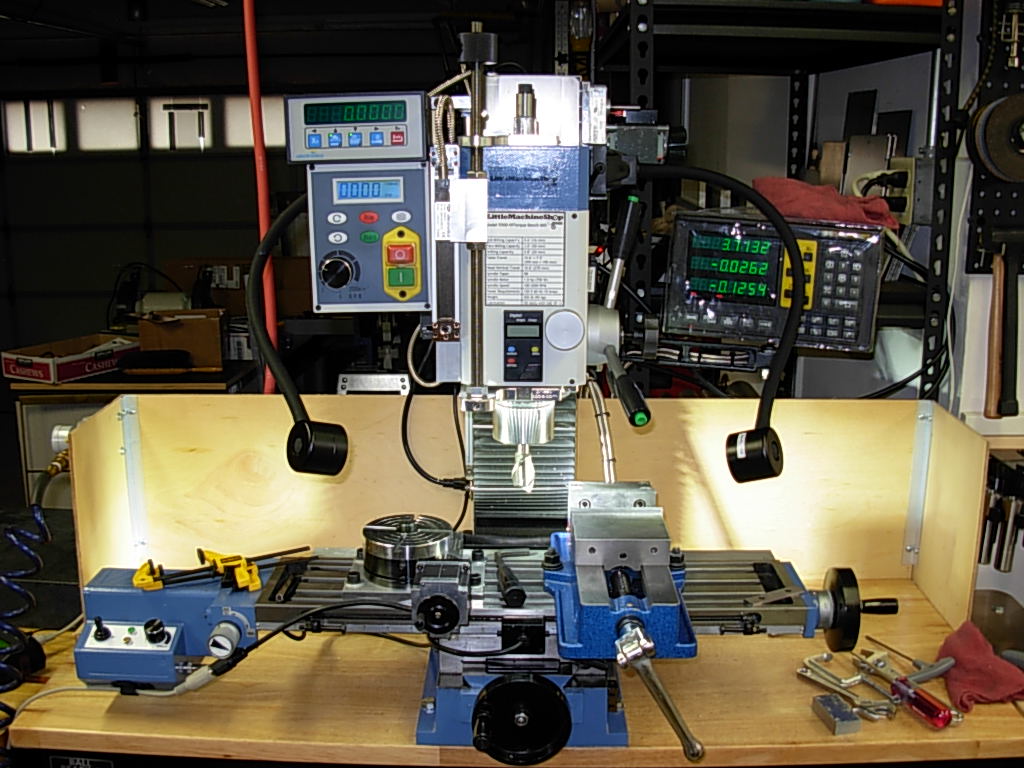
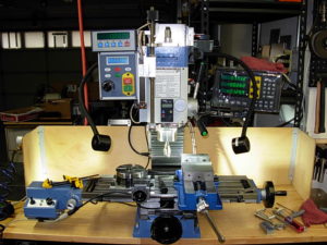
For my purposes this mill is a good selection for what I do as a hobbyist. It has a lot of power and table range. However, being one not to leave well-enough alone (as my father would say) I find the following mods greatly enhance the LMS 5500 mill. Most of these are simple bolt-on kits available from LMS or other suppliers and were not difficult to install.
Notes:
1. Click on any picture to enlarge.
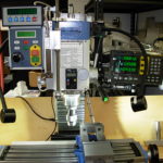
Magnetic DROs for X/Y/Z & Quill
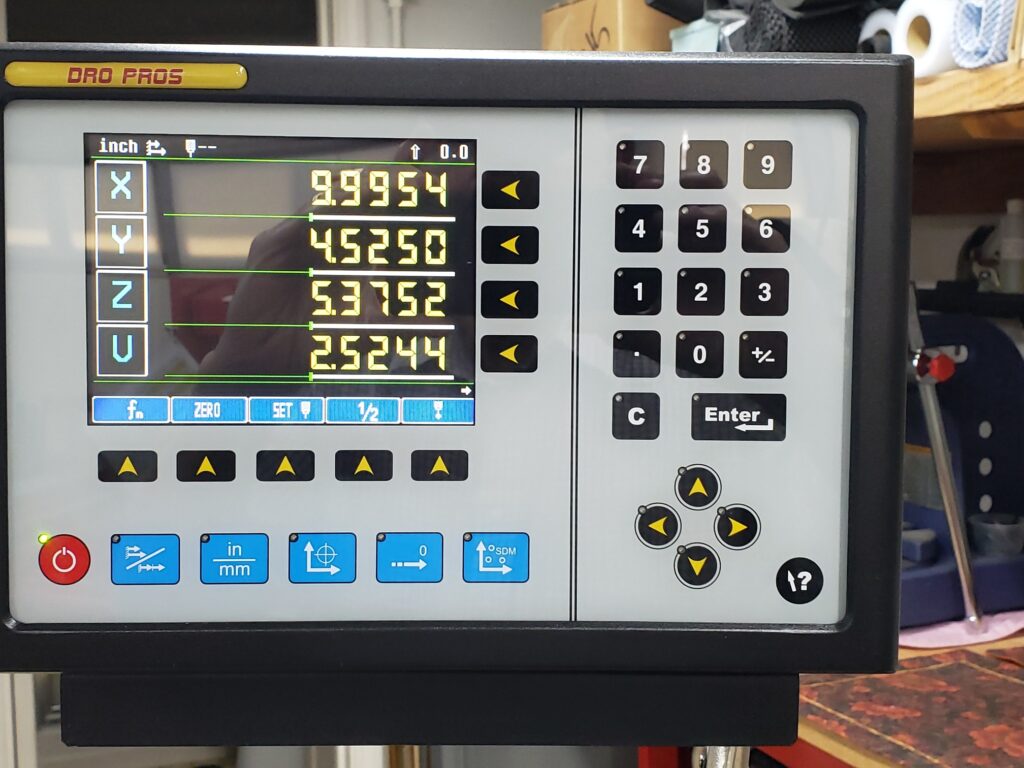
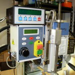
DROs (Digital Read Outs) are a very worth-while asset to this mill and are fairly easy to install. I selected the DRO PROS 3-axis EL400 and then added a single axis EL10 for the quill. Follow the DRO PROS instructions and you will have no trouble.
Installation Notes:
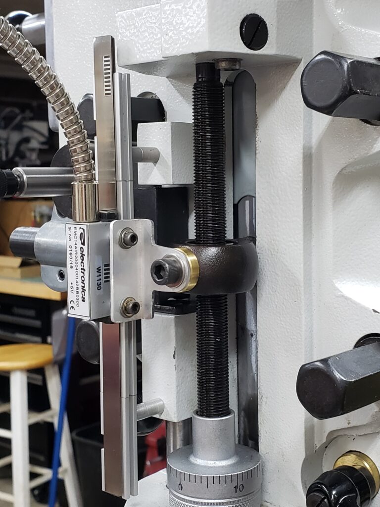
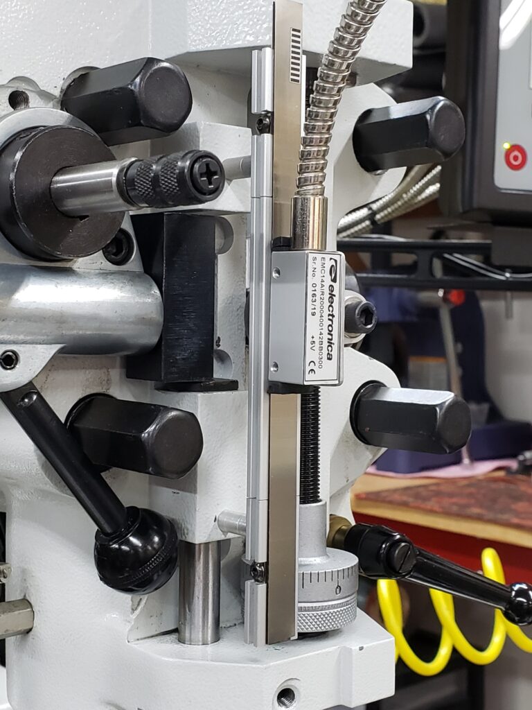
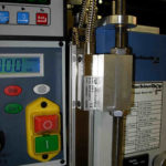
The quill DRO was easily attached since I had already installed the Spindle Lock (shown below). I only had to add an aluminum bracket to hold the scale and make a part to hold the scale sensor which attaches to the quill stop . The EL10 display is attached to the top of the mill control box via Velcro strips.
-
-
Front
-
-
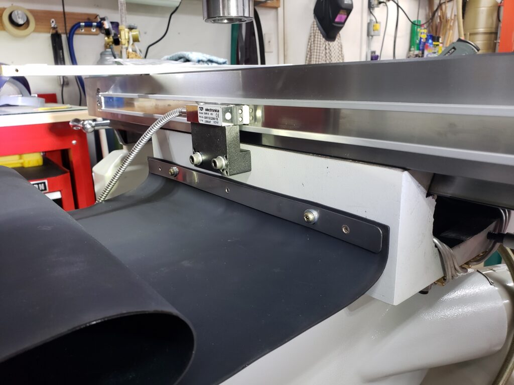
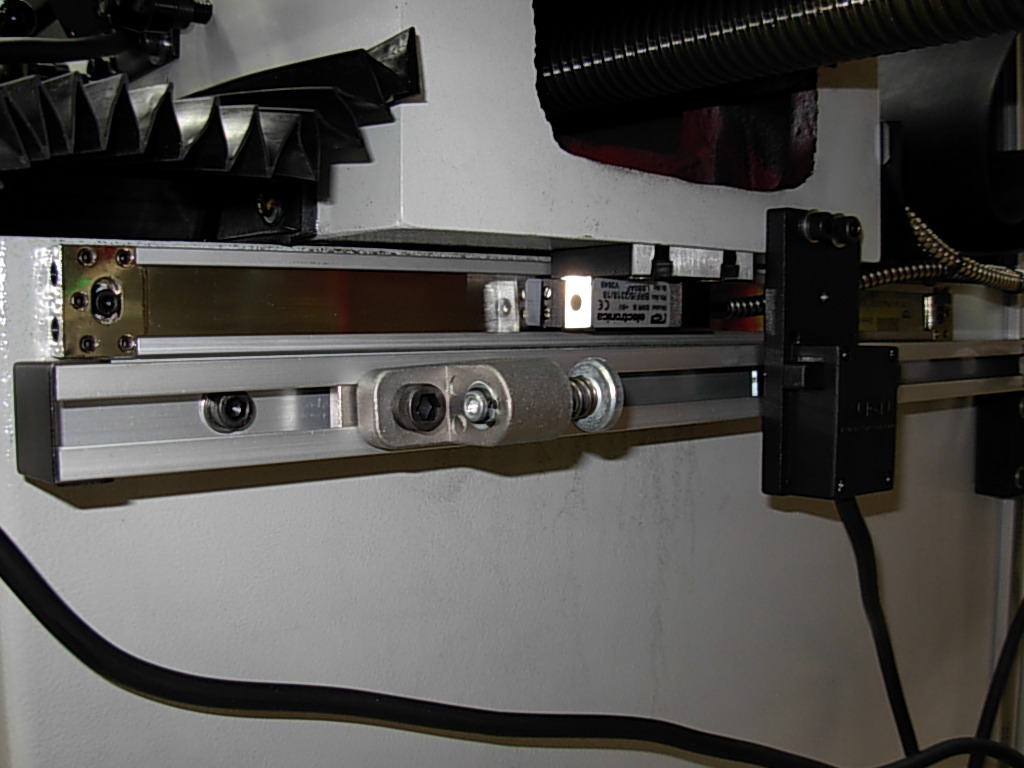
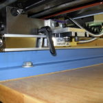
Y-Axis DRO Scale
-
-
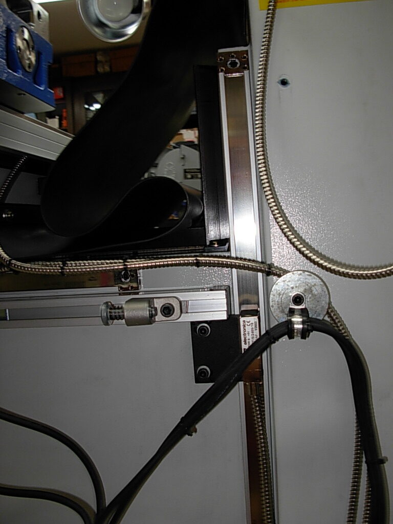
Z-Axis DRO Scale
-
-
Left Side
-
-
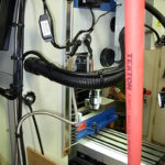
Quill DRO
-

-
Quill DRO
-
-
Quill DRO
-
-
Quill DRO
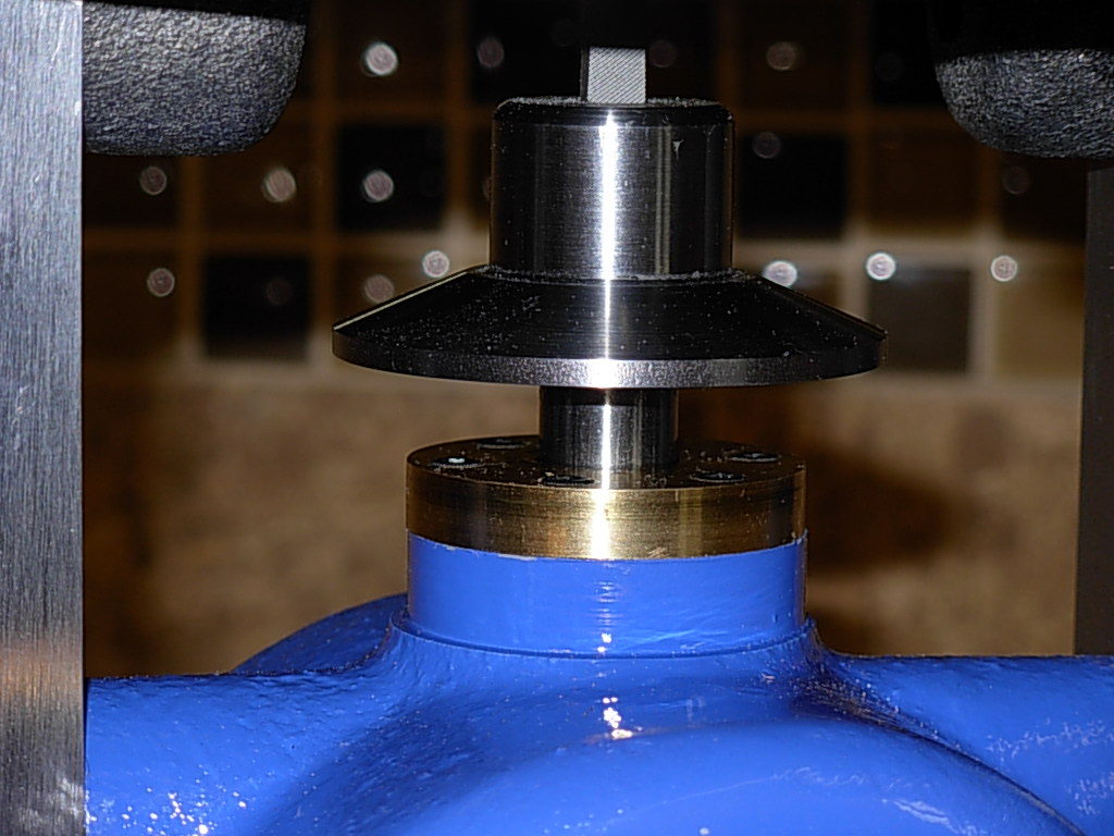
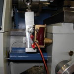
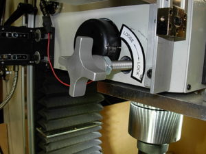
Spindle Lock, HiTorque Bench Mill, Flip Style
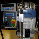
Another nice option is spindle lock LMS 5655. It will free up one hand when changing tools and also turn off the mill when engaged. This is a simple installation if you follow the supplied instructions.
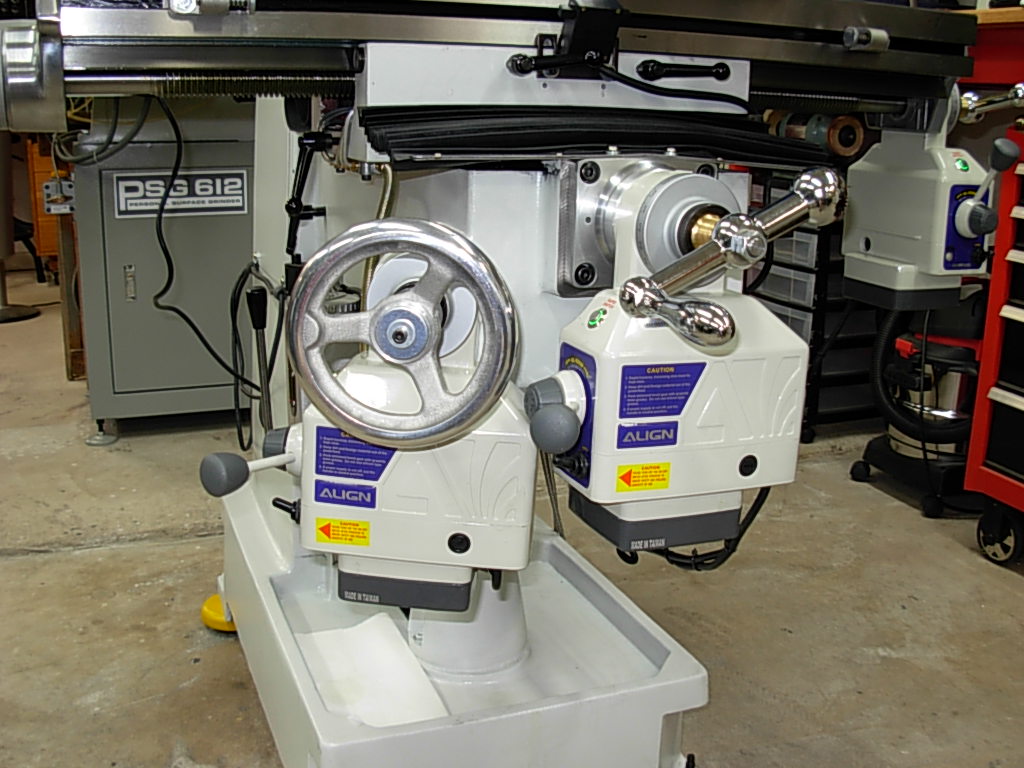
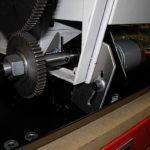
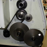
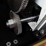
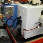
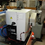
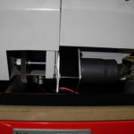
Power Lift System, HiTorque Bench Mil
Probably the handiest addition is the z-axis power lift system LMS 5657. The hand-wheel for the z-axis is located on the top r/h side of the column and not handy at all. This is a simple installation if you follow the supplied instructions.
Installation Notes:
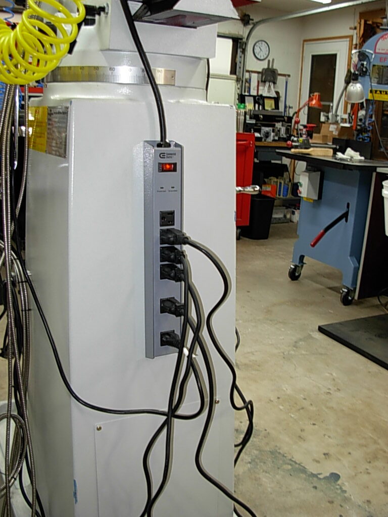
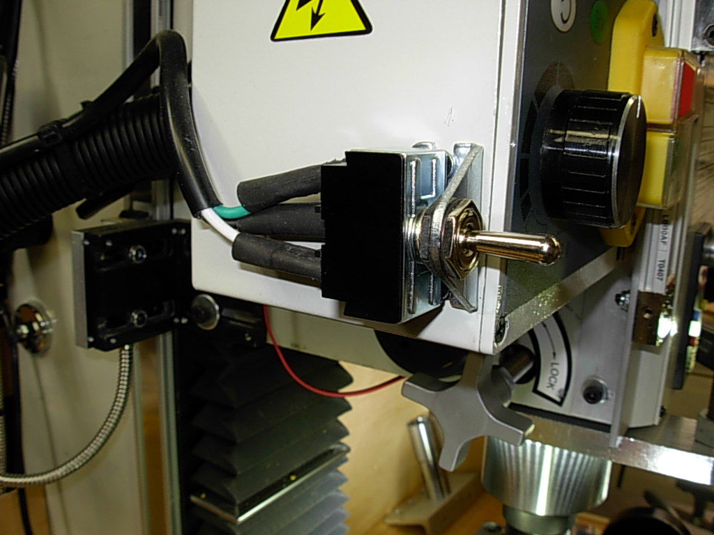
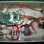
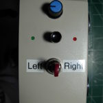
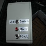
I did move the up/down power switch to a more convenient location on the side of the mill control box.

Z-Axis Up-Down switch
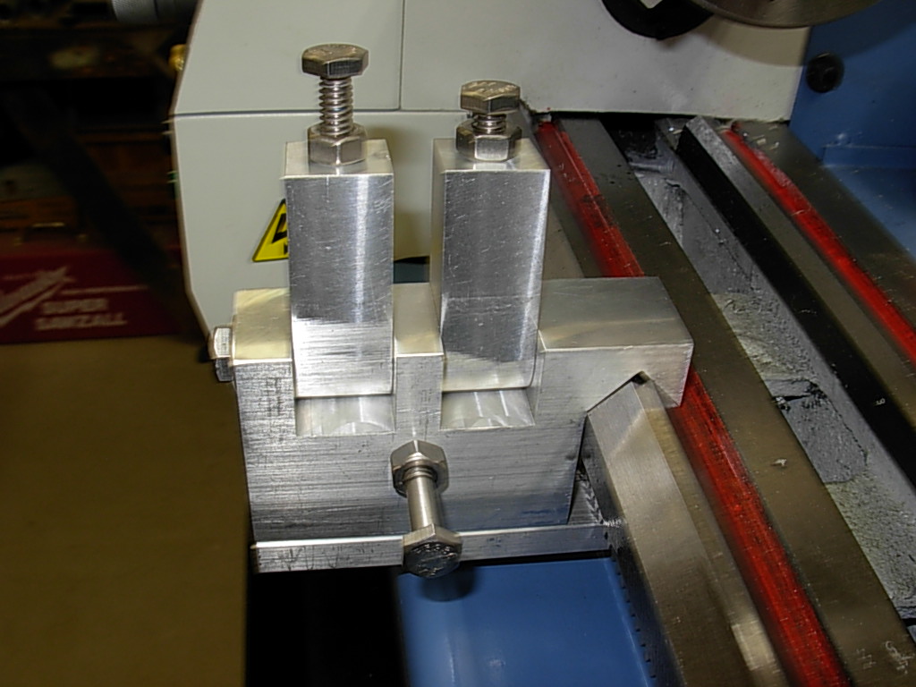
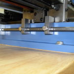
X & Y Axis Hard Stops
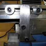
If you’re into building steam engines or other miniature projects I find hard stops are a must. Trying to machine a pocket requiring multiple passes is tedious and requires careful attention to which way you turn the table wheels. Turning the wheel the wrong way can ruin the looks of your pocket.
One answer is to install hard stops on both the X and Y axis.
-
-
X-Axis
-
-
X-Axis Adjustable Stop
-
-
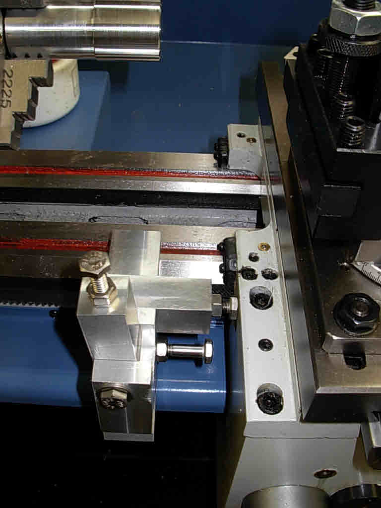
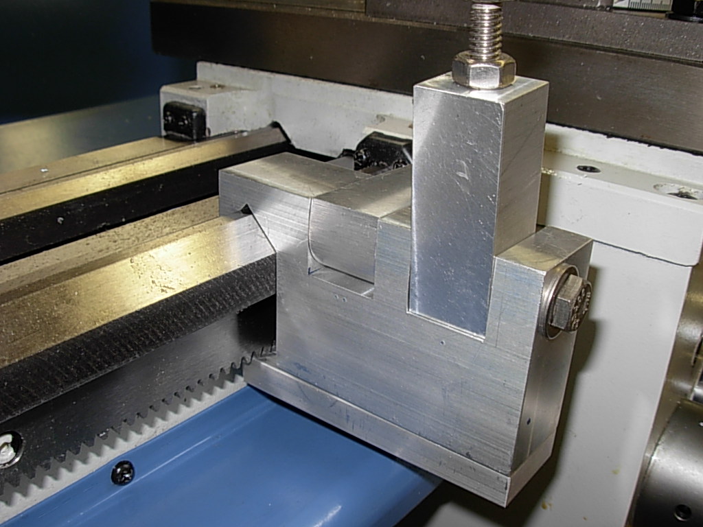
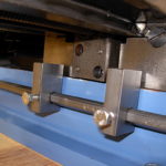
Y-Axis Stop Assembly
-
-
Y-Axis Detail
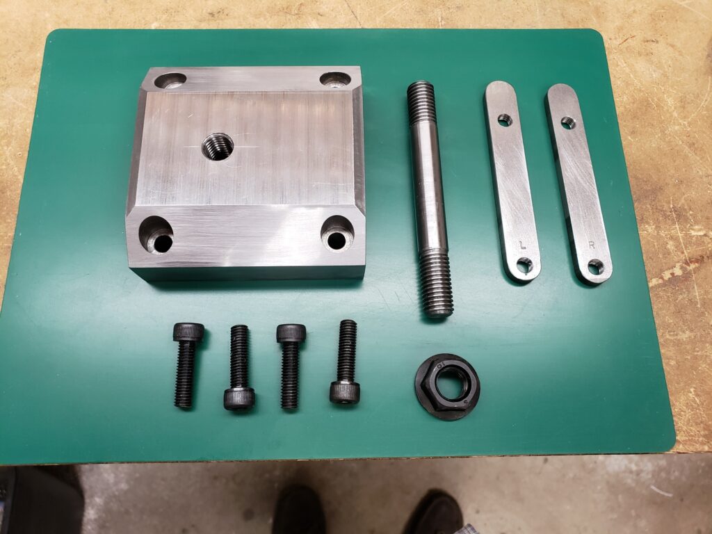
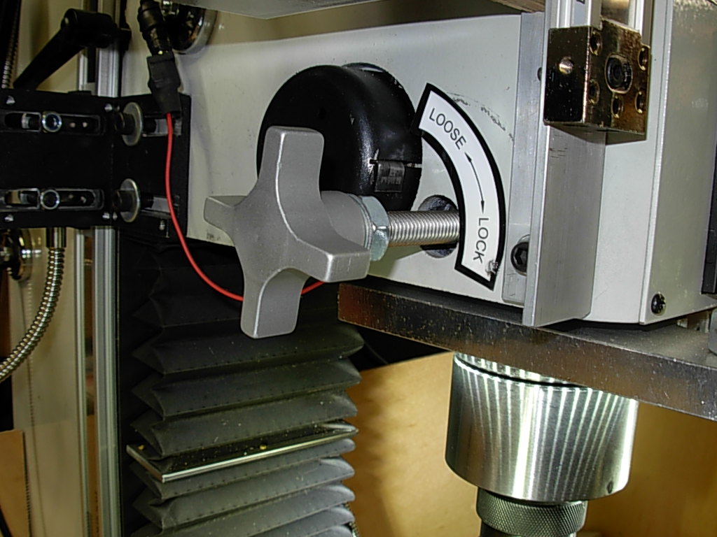
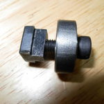
Quill Lock
The factory supplied quill lock, in my opinion, is clumsy and hard to use. I elected to replace it with a piece of 10 mm all-thread and aluminum handle from McMaster Carr. This replacement provides plenty of torque and you don’t have to find an Allen wrench every time you want to lock the quill.
New Spindle Lock
Lighting
Very important is table lighting when working on the mill. Not being satisfied with my shop lighting I installed a pair of magnetic base Goose-Neck LED lights. I attached them to the top of the column one on each side and they provide very adequate working light.
I also installed a 12 vdc LED Ring Light to the bottom side of the Quill Lock plate which adds a little auxiliary light (if you’re not to close to the table), but can’t compare with the goose-neck’s.
Lights